
Courtesy: Keysight
Introduction


LIDAR (Light Detection and Ranging) has become a cornerstone technology for autonomous vehicles, enabling high-resolution spatial mapping and object detection. As the industry pushes toward scalable, cost-effective solutions, LIDAR on a chip has emerged as a compelling alternative to traditional mechanical systems. Its advantages—compactness, robustness, and the absence of moving parts—make it an excellent candidate for large volume manufacturing.
However, achieving a commercially viable on-chip LIDAR requires careful optimisation. Designers must minimise insertion loss, maximise output optical power, broaden beam steering range, and narrow the emitted beam. To meet these challenges, reliable and specialised photonic simulation tools are essential for reducing development cycles and ensuring high-performance designs.
Overall Design and Simulation Strategy
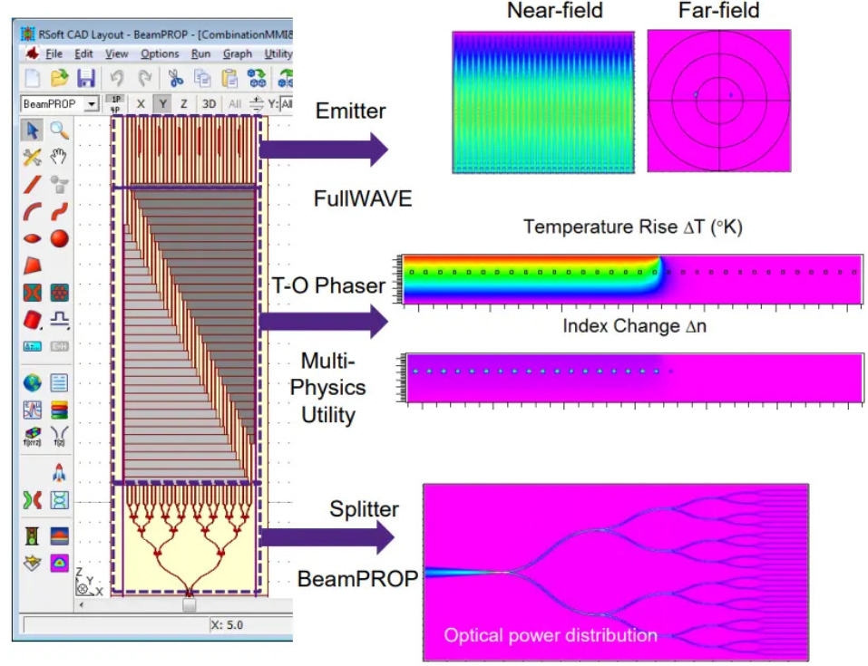
To efficiently design a LIDAR-on-chip system, the device is decomposed into functional blocks, each simulated using the most appropriate tool from the RSoft Photonic Device Tools suite:
Cascaded 1×32 splitter: BeamPROP BPM
BPM is ideal for 1×2 splitters due to little backward reflection and suitability for slowly varying structures.
Thermo-optical phase shifter: BeamPROP BPM + Multiphysics Utility
BPM handles optical propagation, while the Multiphysics Utility computes temperature-dependent refractive index perturbations.
Emitter (grating antenna array): FullWAVE FDTD
FDTD (Finite Difference Time Domain) is required for omnidirectional light propagation and accurate grating coupler modelling.
This modular approach ensures each component is optimised using the most accurate and computationally efficient method available.
Step-by-Step Design of Individual Components
Power Splitter
A splitter tree is constructed using cascaded 1×2 splitters—either MMI or Y‑branch designs.
1×2 MMI splitters
- Low insertion loss (~0.3 dB)
- Robust to asymmetric input
- More complex to design
- Wavelength sensitive, limited bandwidth, polarisation dependent
Y‑branch splitters
- Simple geometry (two S‑bends)
- Broadband and polarisation independent
- Higher insertion loss (~2 dB)
- Less tolerant to asymmetric input
Both structures are well-suited to BeamPROP BPM, which solves one-way wave equations under assumptions of slow structural variation and monochromatic excitation.
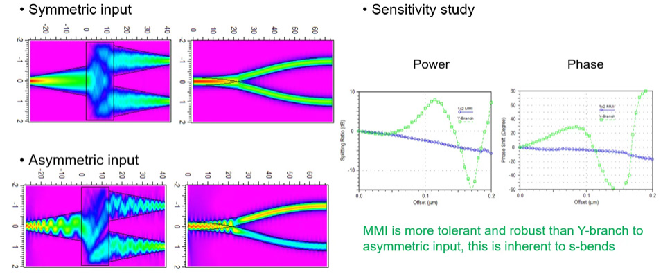
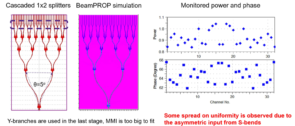
After optimising width and length using 2.5D (2D‑EIM) BPM, sensitivity analyses were performed for symmetric and asymmetric inputs. The final 1×32 splitter tree uses four levels of 1×2 MMIs, followed by a fifth level of Y‑branches where MMIs become too large to fit the remaining layout area.
Thermo-Optical Phase Shifter
Silicon’s strong thermal sensitivity (dn/dT = 0.00024/K) enables phase tuning by heating waveguide arrays. Unequal heating introduces phase delays between channels, steering the output beam.
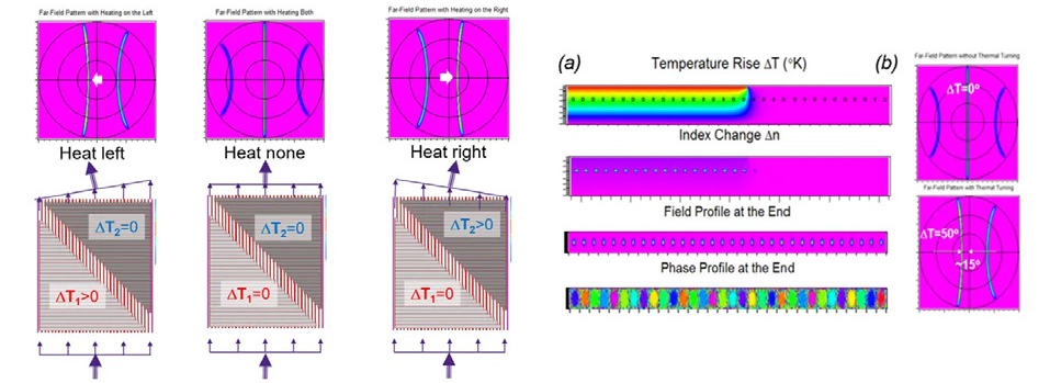
The workflow:
- The thermal diffusion equation was solved to obtain the temperature distribution.
- Temperature profile converted into refractive index perturbation.
- BPM simulates optical propagation to compute amplitude and phase at the output.
- Far‑field analysis reveals the resulting beam steering.
For a temperature change of ΔT = 50 °C, the phase difference between adjacent waveguides is 120°. BPM predicts a steering angle of 15°, matching the theoretical value:
Emitting Gratings
To efficiently outcouple light (orthogonally) with minimal divergence, the grating must be properly apodized. FDTD optimisation yields an optimal tapered-width grating profile, normalised to the grating length (Fig. 5).