
Description
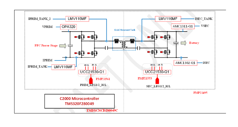
The PMP21495 reference design is a 6.6 kW bi-directional dual-active-bridge resonant converter reference design that allows 380 VDC to 600 VDC input and 280 VDC to 450 VDC output. This design uses C2000 Microcontroller TMS320F280049 along with silicon-carbide (SiC) driver UCC21530-Q1 to drive bridges both on primary and secondary sides. Daughter card approach has been implemented to C2000 controller (TMDSCNCD280049C) and SiC drivers (PMP21553 and PMP21561). Rogowski coil is applied for synchronous rectifier (SR) optimization along with high bandwidth OpAmp LMV116MF. With 500 kHz resonant frequency and 300 kHz~700 kHz operational frequencies, this design is able to reach peak 98% efficiency.


 1. System Specification
1.1 Board Dimension
Board dimension should be within 5.8” x 10.7” x 3”.
1.2 Input/Output Characteristics
- 380VDC to 600VDC
- 280VDC to 450VDC
- Maximum 6.6kW output power.
- >97 % peak efficiency.
1.3 Protections
Provide over-current-protection (OCP) and over-voltage-protection (OVP) functions both at primary and secondary sides.
2. Testing and Results
2.1 Board Photos
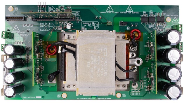
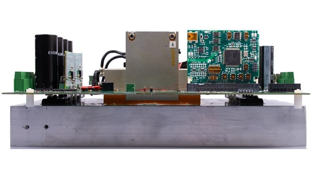
The photographs below show the top and side view of the PMP21495Rev B board.
2.1.1 Top View
2.1.2 Side View
 2.2 Efficiency Data
During efficiency test, 3 x 12V fans (Delta FFB0412EN-00Y2E, operate at 12V) were apply to bottom heatsink and blow from the primary side. A DC power supply is applied on the primary side and a DC load is applied on the secondary side.
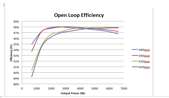
2.2.1 Open Loop Efficiency Measurement
Efficiency was first measured in open loop at a given frequency.
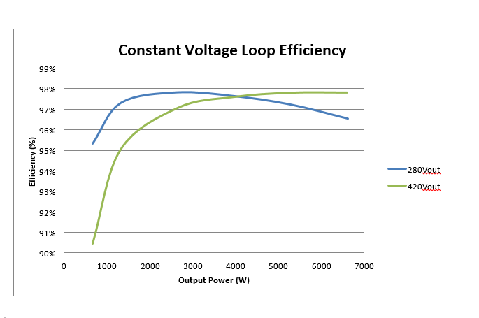
2.2.2 Constant Voltage Loop Efficiency Measurement
The constant voltage loop efficiency measurement was taken with a closed voltage loop with a give target output voltage.
 2.3 Thermal Images
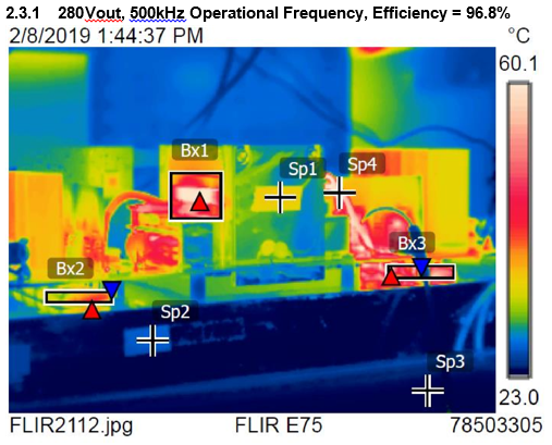
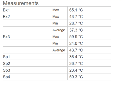
The thermal images below were taken with 6.6kW output power. During the test, 3 x 12V fans (Delta FFB0412EN00Y2E, operate at 12V) were apply to bottom heatsink and blow from the primary side. The ambient temperature was 25ºC
 2.4 Key Waveforms
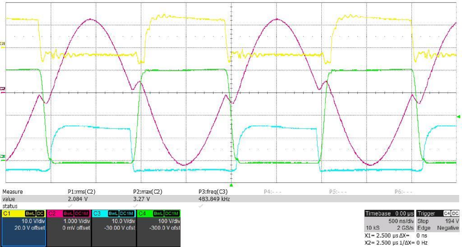
2.4.1 Soft-switching waveforms at 374.788Vin, 280.056Vout/1315.1W, Eff=97.323%:C1 Q101_VGS, C2: Ipri measured with Rogowski Coil with 100mV/A scale, C3: Q105_VGS, C4: Q105_VDS.
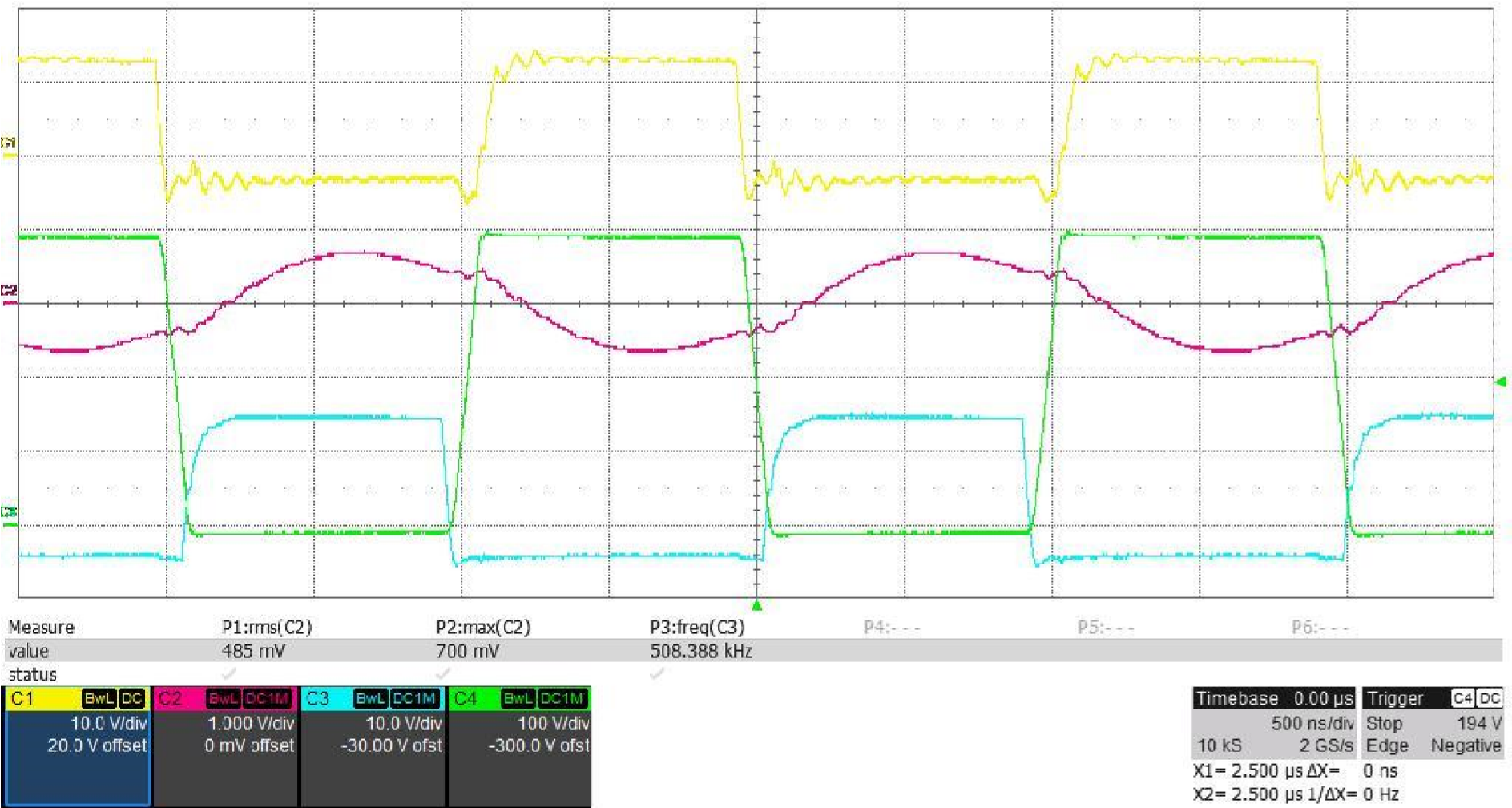
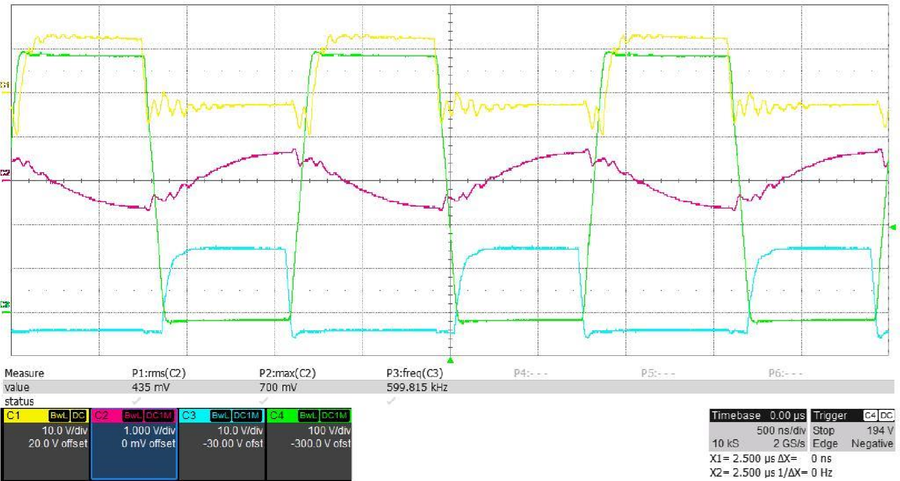
2.4.2 Soft-switching waveforms at 388.456Vin, 280.016Vout/6592.7W, Eff=96.348%: C1: Q101_VGS, C2: Ipri measured with Rogowski Coil with 100mV/A scale, C3: Q105_VGS, C4: Q105_VDS.
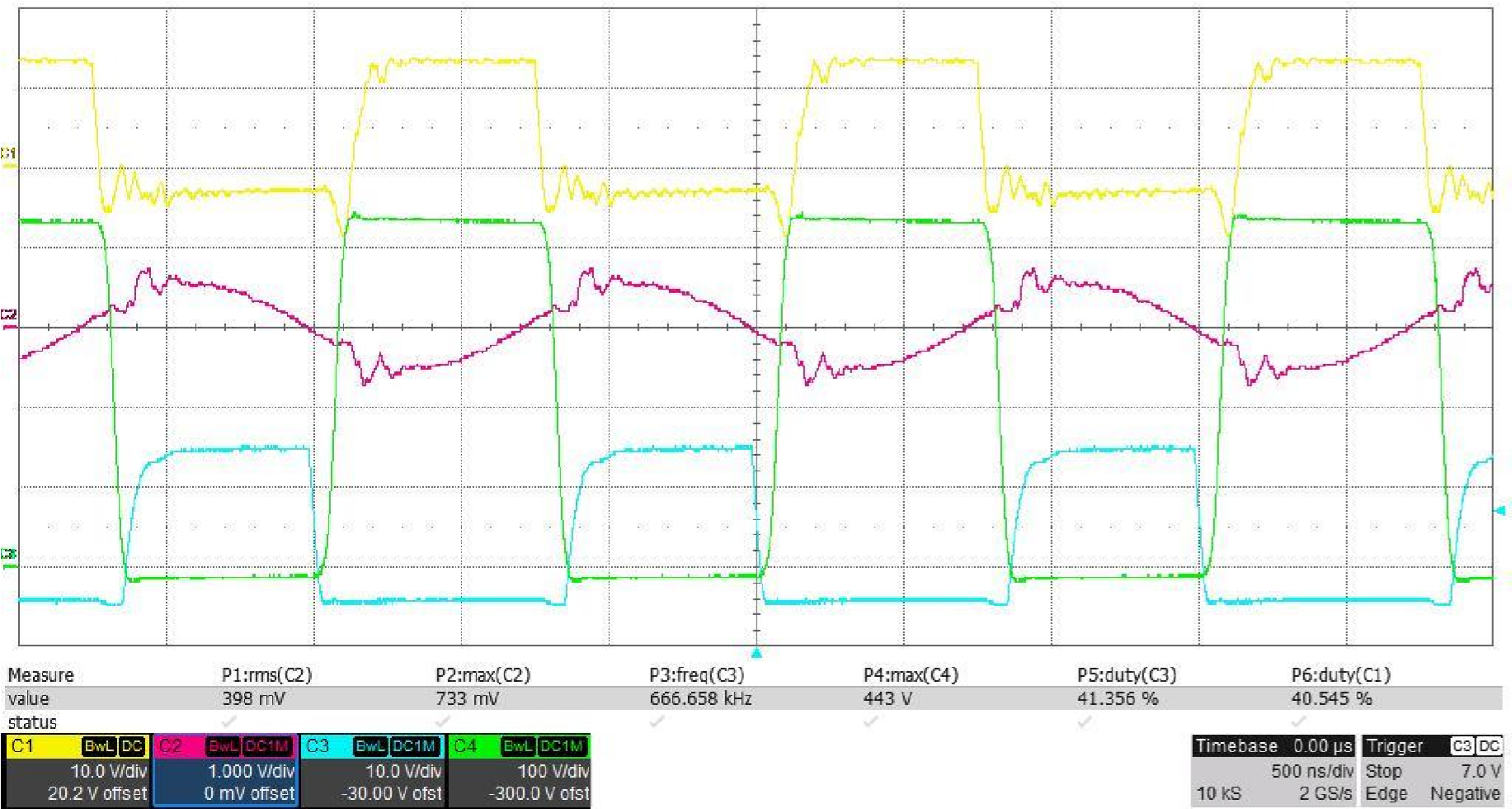
 2.4.3 Soft-switching waveforms at 566.799Vin, 420.150Vout/1323.6W, Eff=95.322%: C1: Q101_VGS, C2: Ipri measured with Rogowski Coil with 100mV/A scale, C3: Q105_VGS, C4: Q105_VDS.
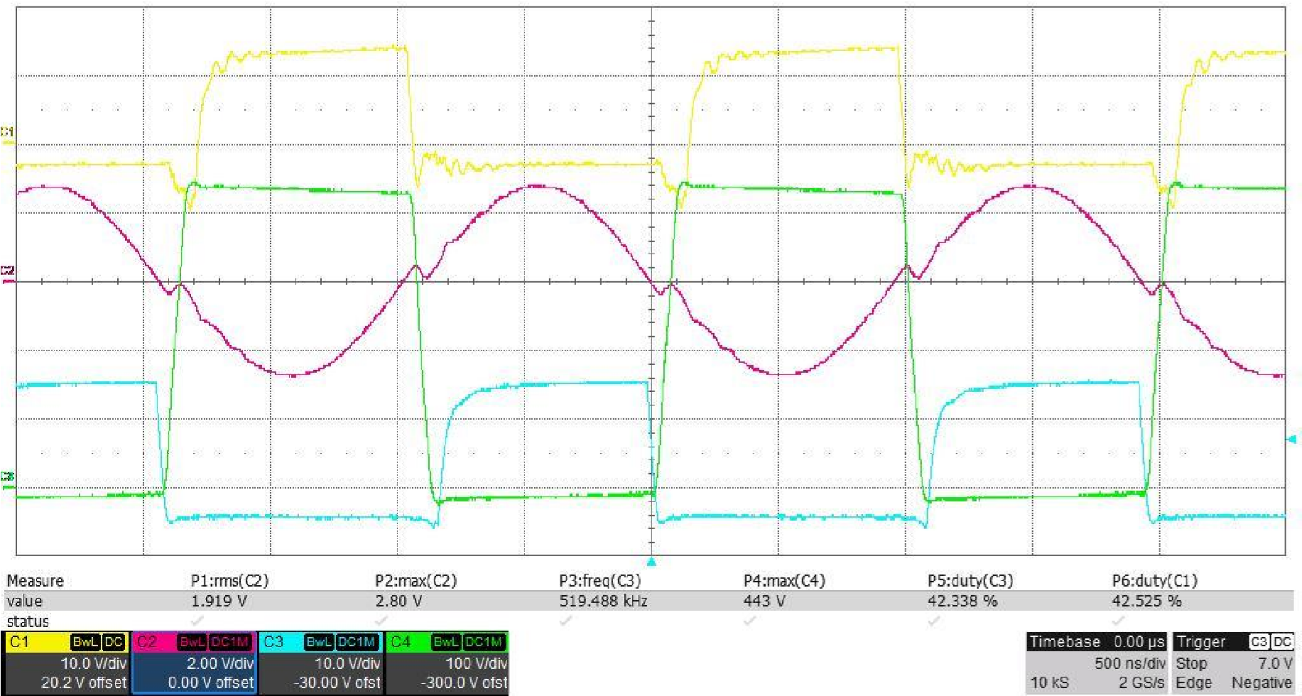
 2.4.4 Soft-switching waveforms at 569.161Vin, 420.012Vout/6613.7W, Eff=97.696%: C1: Q101_VGS, C2: Ipri measured with Rogowski Coil with 100mV/A scale, C3: Q105_VGS, C4: Q105_VDS.
 2.4.5 Soft-switching waveforms at 567.476Vin, 420.047Vout/1332.7W, Eff=93.927%: C1: Q107_VGS, C2: Isec measured with Rogowski Coil with 100mV/A scale, C3: Q103_VGS, C4: Q103_VDS.
2.4.6 Soft-switching waveforms at 568.323Vin, 420.010Vout/6584.7W, Eff=97.888%: C1: Q107_VGS, C2: Isec measured with Rogowski Coil with 100mV/A scale, C3: Q103_VGS, C4: Q103_VDS.
Courtesy: www.ti.com